CALIBRATION
The built-in redundancy of the physics prototype calibration and readout system
allows several different monitoring concepts to be applied and cross-checked.
The calibration capabilities of new developed photodetectors (MGPDs, see below)
can be of manifold use, from production quality control to commissioning
diagnostics, linearity correction and temperature monitoring.
Novel photodetector MGPD and its calibration
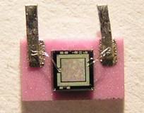 The scintillator based hadron calorimeter relies on the use of novel Multi-Pixel
Geiger mode silicon Photo-Detectors (MGPDs). The MGPD (often called Silicon Photomultiplier
- SiPM)
is a pixilated avalanche photo-diode operated in limited Geiger mode (see figure on the
left). The detector surface of lxl mm² is divided into 1156 pixels. We gained
experience with this photodetector building small test calorimeter MiniCal with
about 100 MGPD channels [see MiniCal].
The scintillator based hadron calorimeter relies on the use of novel Multi-Pixel
Geiger mode silicon Photo-Detectors (MGPDs). The MGPD (often called Silicon Photomultiplier
- SiPM)
is a pixilated avalanche photo-diode operated in limited Geiger mode (see figure on the
left). The detector surface of lxl mm² is divided into 1156 pixels. We gained
experience with this photodetector building small test calorimeter MiniCal with
about 100 MGPD channels [see MiniCal].
The analog output is obtained by adding the response of all pixels fired as
independent digital counters. The MGPD are operated at 2-3 volts above breakdown
voltage (typically at 55 V). By being the internal pixel capacitance
Cpixel of typically 50 fF the charge collected for
one photo-electron signal is ~160 fC (or ~106 electrons).
The MGPD offers a very fast response with a typical rise time of the
order of a nanosecond. The fall time of the signal depends on the pixel
quenching resistor and can be tuned to the needs of the experimental
application (typical values are between 2-150 ns). The dynamic range
is determined by the finite number of pixels and is ~200 pC.
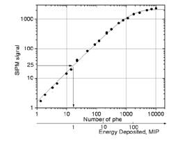
MGPDs have virtues as well as drawbacks. The left figure above displays
the MGPD signal as a function of the number of photoelectrons released from the
photocathode. The signal becomes saturated at high light intensities as a
result of finite number of pixels. At low light intensities one can distinguish
individual photoelectrons on the photocathode equally spaced. This allows
obtain the gain. MGPDs with their high intrinsic gain are sensitive to
temperature and bias voltage fluctuations. The typical values are -1.7% per
temperature increase of 1°C and 2.5% per 0.1V change of bias voltage.
Therefore, calibration and monitoring systems (see next section) are of central
importance. Their layout has important consequences for mechanical structures
and electronics specifications. Careful evaluation of present running
experience and characterization of different hardware solutions must enter into
final conceptual design choices, and it may be appropriate to pursue more than
one option during the next R&D cycle.
Calibration and Monitoring Board
The task of calibration is to obtain gain and measure the nonlinearity
of each MGPD. The aim of monitoring is to record response of a MGPD on long
time scale and provide correction factors for gain which changes due to the
temperature, bias voltage fluctuations and also due to non predictable
situations. The Calibration and Monitoring Board (CMB) provides short steered
pulses for UV LEDs and the light is carried by clear fibers to each
scintillator tile.
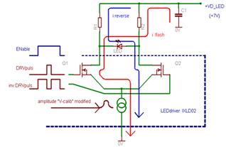
The pulses are provided by a LED driver which has fast rise and fall
edges of the rectangular signal of ~ 10 ns width. The amplitude can be tuned
from zero to 6 V. Each LED is monitored by a PIN diode. The corresponding light
intensity in the tile changes from several photons to the equivalent of light
produced by the passage of up to 100 minimum ionizing particles. The low
intensity light is used to observe single photoelectron peaks in the MGPD which
are equally spaced and allow obtaining gain of each MGPD. With a sweeping from
low up to high intensities the saturation curve of a MGPD can be measured.
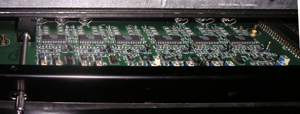
Each detection plane with 216 MGPDs has on a side one CMB which is
divided to two printed boards. The upper one is shown in the figure with
circuits for 6 LEDs. The LED driver is controlled by DAQ via CAN bus which
allows to control parameters like enabling, pulse width and amplitude. The
board contains also the temperature readout from sensors connected to the
photodetectors.
Operational experience and calibration
The HCAL was assembled and commissioned at DESY, where also an initial
calibration of the active layers was obtained in the electron test beam. In
2006, together with ECAL and TCMT, the stack with 23 instrumented layers was
exposed to electron and hadron beams of 6-45 GeV and 6-120 GeV, respectively, in
the H6 beam line at the CERN SPS. In addition high intensity muon beams were
available for calibration.
All calorimeter cells have been calibrated with muons. The
minimum ionizing particle (MIP) signal AMIP
is used as a scale for the deposited energy and to set the noise suppression
threshold of ½ MIP, which yields a MIP hit efficiency of about 95%. The
noise hit occupancy is then about 10-3, corresponding
to ~0.5 GeV on the electromagnetic (em) energy scale. The gain Apixel
is measured with low intensity LED light and used for non-linearity correction.
The energy per cell in units of MIPs is then obtained from the formula
E [MIP] = A/AMIP ∗ F
(Npixel) with Npixel = A/Apixel
where A is amplitude measured in ADC counts. The non-linearity
correction F depends only on the amplitude in units of pixels and is 1
for small amplitudes (all scale factors are absorbed in the MIP calibration
factor). The function F is the inverse of the normalized response
function and can be approximated as F= −
N/Npixel * log (1−Npixel/N)
for a total of N active pixels on the MGPD. In practice Fis obtained
from the test bench measurements. The conversion from MIPs to deposited
energy depends on the incident particle type and is taken from simulations or
using the known beam energy as reference. MIP and pixel scale are subject to
temperature variations of a few percent per Kelvin. The redundant monitoring
system offers various possibilities for correcting these effects, using gain,
LED reference signals or direct temperature measurement.